Utility Model Patent
Application number: 202122540785.X
Application date: 2021.10.21
Patent holder: Jiangxi Tongji Bearing Co., Ltd.
Address: Economic Development Zone, Yushan County, Shangrao City, Jiangxi Province, 335000
Inventor: Cao Jianzhong, Xie Qinghua
Int.Cl.
F16C 33/78 (2006.01)
F16C 33/30 (2006.01)
Utility model name:
A bearing with dust and pollution prevention function
Abstract:
The utility model discloses a bearing with dust and pollution prevention function, including a bearing body a, one end of the bearing body a is embedded with a bearing body b, the bearing body a and the bearing body b are embedded with a shaft core, the top and bottom ends of the shaft core are embedded with a limit cover, the inner side of the shaft core is embedded with a limit sleeve, the top of the bearing body a and the bearing body b are fixed with a fixing plate by bolts, and the top of the fixing plate is installed with a dust cover. The utility model can provide an installation position for the dust cover through the fixing plate to ensure the stability of the dust cover, and a shield is installed at the bottom of the dust cover, and the bottom end of the shield is embedded in the inner side of the embedding groove c, so that the dust cover and the shield can cover the gap between the shaft core and the bearing body a and the bearing body b, thereby preventing dust and debris from entering the bearing when in use, causing bearing damage, and extending the service life of the bearing.
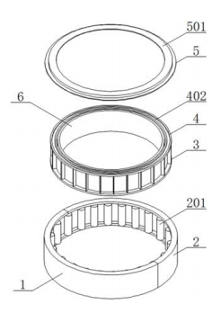
1. A bearing with dust and pollution prevention function, comprising a bearing body a (1), characterized in that: a bearing body b (2) is embedded and installed at one end of the bearing body a (1), and a shaft core (3) is embedded and installed inside the bearing body a (1) and the bearing body b (2);
A limit cover (4) is embedded and installed at the top and bottom ends of the shaft core (3), and a limit sleeve (6) is embedded and installed inside the shaft core (3);
A fixing plate (5) is fixed to the top of the bearing body a (1) and the bearing body b (2) by bolts, and a dust cover (501) is installed on the top of the fixing plate (5).
2. A bearing with dust and pollution prevention function according to claim 1, characterized in that: a fitting block (101) is installed at one end of the bearing body a (1).
3. A bearing with dust and pollution prevention function according to claim 1, characterized in that: an engaging groove a (202) is provided at one end of the bearing body b (2), and a limiting groove a (203) is provided on the inner side of the bearing body a (1) and the bearing body b (2), and a roller (201) is movably installed on the inner side of the limiting groove a (203).
4. A bearing with dust and pollution prevention function according to claim 1, characterized in that: a limiting plate a (301) is evenly installed on the outer wall of the shaft core (3), and the roller (201) is located on the inner side of the limiting plate a (301), engaging grooves b (302) are provided at both ends of the shaft core (3), and a limiting block (303) is installed on the inner wall of the shaft core (3).
5. A bearing with dust and pollution prevention function according to claim 1, characterized in that: a limit plate b (401) is installed at the bottom end of the limit cover (4), and the limit plate b (401) is embedded in the inner side of the embedding groove b (302), and the top of the limit cover (4) is provided with an embedding groove c (402).
6. A bearing with dust and pollution prevention function according to claim 1, characterized in that: a shield plate (502) is installed at the bottom of the dust cover (501), and the bottom end of the shield plate (502) is embedded in the inner side of the embedding groove c (402).
7. A bearing with dust and pollution prevention function according to claim 1, characterized in that: a limit groove b (601) is provided on the outer wall of the limit sleeve (6).
A bearing with dust and pollution prevention function
Technical field:
[1] The utility model relates to the technical field of bearings, and specifically to a bearing with dust and pollution prevention function.
Background technology:
[2] A bearing is a mechanical element that limits relative motion within a desired range of motion and reduces friction between moving parts. The design of the bearing can provide free linear motion of moving parts or free rotation around a fixed axis, and can also prevent motion by controlling the vector of the normal force acting on the moving parts. However, existing bearings do not have dust and pollution prevention functions when in use, resulting in dust and debris entering the bearing during use, thereby causing damage to the bearing and reducing the service life of the bearing.
[3] The defects of bearings in the prior art are:
[4] 1. Patent document CN109578441A discloses a bearing that "includes a bearing outer ring and a bearing inner ring, wherein the bearing outer ring and the bearing inner ring are both composed of an outer ring and an inner ring, 12 steel balls are evenly arranged between the outer ring and the inner ring, the centers of the steel balls are connected by a slot, and are located at a fixed position of the slot, and rotate with the slot as the rotation axis; a fixed ring is arranged outside the bearing outer ring, and a plurality of lubrication holes are arranged on the fixed ring. The bearing described in the invention is provided with a bearing outer ring and a bearing inner ring, which can work simultaneously or separately, thereby expanding the application range of the bearing. The steel balls of the bearing are fixed on the slot and rotate with the slot as the center, thereby preventing the steel balls from deviating from their original positions after the bearing is used for a long time, thereby affecting the use of the bearing. The lubrication holes are arranged on the bearing, which can lubricate the inside of the bearing while the bearing is working, thereby avoiding the cost increase and weight increase caused by the traditional lubrication method." However, when in use, it does not have the function of dust and pollution prevention. , causing dust and debris to enter the bearing when in use, thereby causing bearing damage and reducing the service life of the bearing;
[5] 2. In the prior art, it is generally not convenient for workers to disassemble and maintain the bearing when in use. When the bearing is damaged, it is not convenient for workers to repair the bearing.
Utility Model Content
[6] The purpose of the utility model is to provide a bearing with dust and pollution prevention functions to solve the problems raised in the above background technology.
[7] To achieve the above purpose, the utility model provides the following technical solutions: a bearing with dust and pollution prevention functions, comprising a bearing body a, one end of the bearing body a is embedded with a bearing body b, and the bearing body a and the bearing body b are embedded with a shaft core;
[8] The top and bottom ends of the shaft core are embedded with a limit cover, and the inner side of the shaft core is embedded with a limit sleeve;
[9] The tops of the bearing body a and the bearing body b are fixed with a fixing plate by bolts, and the top of the fixing plate is installed with a dust cover.
[10] Preferably, an engaging block is installed at one end of the bearing body a.
[11] Preferably, an engaging groove a is provided at one end of the bearing body b, and a limiting groove a is provided on the inner side of the bearing body a and the bearing body b, and a roller is movably installed on the inner side of the limiting groove a.
[12] Preferably, a limiting plate a is evenly installed on the outer wall of the shaft core, and the roller is located on the inner side of the limiting plate a, and engaging grooves b are provided at both ends of the shaft core, and a limiting block is installed on the inner wall of the shaft core.
[13] Preferably, a limiting plate b is installed at the bottom end of the limiting cover, and the limiting plate b is embedded in the inner side of the embedding groove b, and an embedding groove c is provided at the top of the limiting cover.
[14] Preferably, a shield is installed at the bottom of the dust cover, and the bottom end of the shield is embedded in the inner side of the embedding groove c.
[15] Preferably, a limiting groove b is provided on the outer wall of the limiting sleeve.
[16] Compared with the prior art, the beneficial effects of the present invention are as follows:
[17] 1. The present invention can provide an installation position for the dust cover through the fixing plate to ensure the stability of the dust cover. A shield is installed at the bottom of the dust cover, and the bottom end of the shield is embedded in the inner side of the embedding groove c, so that the dust cover and the shield can cover the gap between the shaft core and the bearing body a and the bearing body b, thereby preventing dust and debris from entering the bearing when in use, causing damage to the bearing, and extending the service life of the bearing. [18] 2. The utility model can facilitate the staff to connect the bearing body a and the bearing body b together and to disassemble the bearing body a and the bearing body b by embedding the embedding block in the inner side of the embedding groove a. The limiting plate b is embedded in the inner side of the embedding groove b, so that the connection between the limiting cover and the shaft core is stable and it is convenient for the staff to disassemble the limiting cover, thereby facilitating the staff to take the shaft core out of the inside of the bearing body a and the bearing body b. When the inside of the bearing is damaged, it is convenient for the staff to repair the bearing.
Description of the drawings:
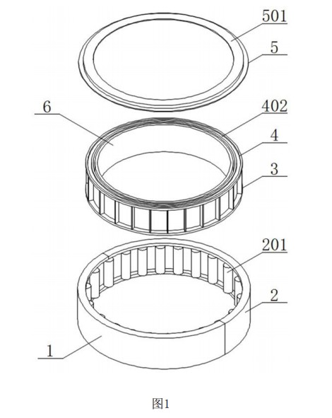
[19] Figure 1 is a schematic diagram of the disassembled structure of the utility model;
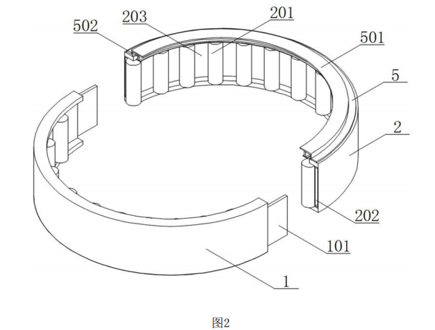
[20] Figure 2 is a schematic diagram of the disassembled structure of the bearing body of the utility model;
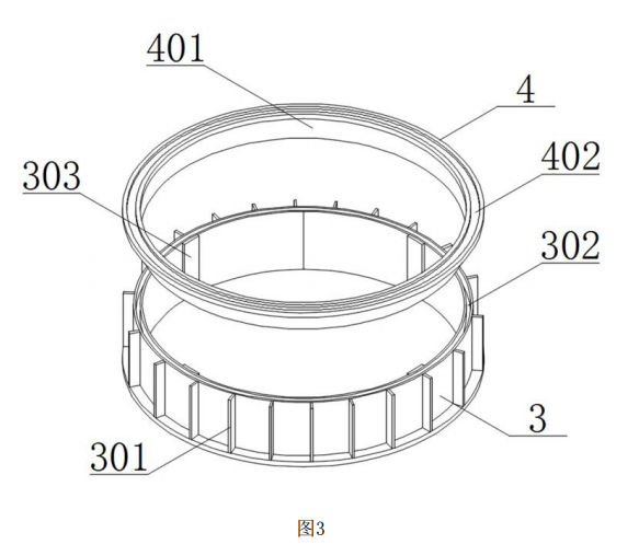
[21] Figure 3 is a schematic diagram of the shaft core structure of the utility model;
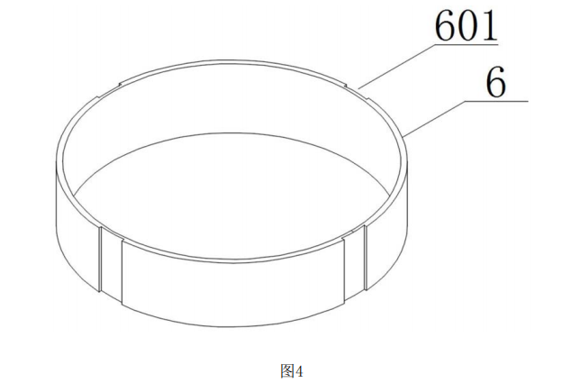
[22] Figure 4 is a schematic diagram of the limit sleeve structure of the utility model.
[23] In the figure: 1, bearing body a; 101, interlocking block; 2, bearing body b; 201, roller; 202, interlocking groove a; 203, limit groove a; 3, shaft core; 301, limit plate a; 302, interlocking groove b; 303, limit block; 4, limit cover; 401, limit plate b; 402, interlocking groove c; 5, fixed plate; 501, dust cover; 502, shielding plate; 6, limit sleeve; 601, limit groove b.
Specific implementation method:
[24] The following will be combined with the drawings in the embodiments of the utility model to clearly and completely describe the technical solutions in the embodiments of the utility model. Obviously, the described embodiments are only part of the embodiments of the utility model, not all of the embodiments. Based on the embodiments in the utility model, all other embodiments obtained by ordinary technicians in this field without making creative work are within the scope of protection of the utility model.
[25] In the description of the utility model, it should be noted that the terms "upper", "lower", "inner", "outer", "front end", "rear end", "two ends", "one end", "the other end" and the like indicate the orientation or position relationship based on the orientation or position relationship shown in the drawings, which is only for the convenience of describing the utility model and simplifying the description, and does not indicate or imply that the device or element referred to must have a specific orientation, be constructed and operated in a specific orientation, and therefore cannot be understood as a limitation on the utility model. In addition, the terms "first" and "second" are only used for descriptive purposes and cannot be understood as indicating or implying relative importance.
[26] In the description of the present invention, it should be noted that, unless otherwise clearly specified and limited, the terms "installed", "provided with", "connected", etc. should be understood in a broad sense. For example, "connected" can be a fixed connection, a detachable connection, or an integral connection; it can be a mechanical connection or an electrical connection; it can be a direct connection, or an indirect connection through an intermediate medium, or it can be the internal connection of two components. For ordinary technicians in this field, the specific meanings of the above terms in the present invention can be understood according to the specific situation. [27] Please refer to Figures 1, 3 and 4, a bearing with dust and pollution prevention functions;
[28] Embodiment 1: A fitting block 101 is installed at one end of the bearing body a1, and a bearing body b2 is fitted at one end of the bearing body a1, and a fitting groove a202 is provided at one end of the bearing body b2. A limiting groove a203 is provided on the inner side of the bearing body a1 and the bearing body b2. The fitting block 101 is fitted on the inner side of the fitting groove a202, so that the staff can connect the bearing body a1 and the bearing body b2 together, and the staff can disassemble the bearing body a1 and the bearing body b2. The limiting groove a203 can provide the roller 201 with a sliding position to ensure the stability of the roller 201. The roller 201 is movably installed on the inner side of the limiting groove a203. The shaft core 3 is fitted inside the bearing body a1 and the bearing body b2. The shaft core 3 The outer wall of the shaft 3 is evenly installed with a limit plate a301, and the roller 201 is located on the inner side of the limit plate a301. The two ends of the shaft core 3 are provided with an engaging groove b302. The inner wall of the shaft core 3 is installed with a limit block 303. The roller 201 is located on the inner side of the limit plate a301 to ensure the stability of the roller 201. The roller 201 can make the shaft core 3 rotate better.
[29] Please refer to Figures 1, 2 and 4, a bearing with dust and pollution prevention functions;
[30] Embodiment 2: The top and bottom ends of the shaft core 3 are fitted with a limit cover 4, the bottom end of the limit cover 4 is installed with a limit plate b401, and the limit plate b401 is fitted inside the fitting groove b302, and the top of the limit cover 4 is provided with a fitting groove c402. The limit cover 4 can ensure the stability of the shaft core 3 inside the bearing body a1 and the bearing body b2. The limit plate b401 is fitted inside the fitting groove b302, so that the stability of the connection between the limit cover 4 and the shaft core 3 is improved, and it is convenient for the staff to remove the limit cover 4, so that it is convenient for the staff to take the shaft core 3 out of the bearing body a1 and the bearing body b2. When the bearing is damaged, it is convenient for the staff to repair the bearing. The inner side of the shaft core 3 is fitted with a limit sleeve 6, and the limit sleeve 6 is fitted inside the shaft core 3. The outer wall of the positioning sleeve 6 is provided with a limiting groove b601, which is engaged with the limiting block 303 through the limiting groove b601 to ensure the stability of the limiting sleeve 6 on the inner side of the shaft core 3. The limiting sleeve 6 can be connected to an external device. The top of the bearing body a1 and the bearing body b2 are fixed with a fixing plate 5 by bolts. The top of the fixing plate 5 is installed with a dust cover 501, and the bottom of the dust cover 501 is installed with a baffle 502, and the bottom end of the baffle 502 is engaged with the inner side of the engaging groove c402. The fixing plate 5 can provide an installation position for the dust cover 501 to ensure the stability of the dust cover 501. The bottom of the dust cover 501 is installed with a baffle 502, and the bottom end of the baffle 502 is engaged with the inner side of the engaging groove c402, so that the dust cover 501 and the baffle 502 can separate the shaft core 3 from the bearing body a1 and the bearing body. The gap between b2 is covered, thereby preventing dust and debris from entering the bearing during use, causing bearing damage and extending the service life of the bearing.
[31] Working principle: by engaging the engaging block 101 in the inner side of the engaging groove a202, it is convenient for the staff to connect the bearing body a1 and the bearing body b2 together, and it is convenient for the staff to disassemble the bearing body a1 and the bearing body b2. By means of the limiting groove a203, the roller 201 can be provided with a sliding position. By means of the roller 201 being located on the inner side of the limiting plate a301, the stability of the roller 201 is ensured. By means of the roller 201, the shaft core 3 can be better rotated. By means of the limiting cover 4, the stability of the shaft core 3 inside the bearing body a1 and the bearing body b2 can be ensured. By means of the limiting plate b401 being engaged in the inner side of the engaging groove b302, the stability of the connection between the limiting cover 4 and the shaft core 3 is ensured, and it is convenient for the staff to disassemble the limiting cover 4, so that it is convenient for the staff to take the shaft core 3 out of the bearing body a1 and the bearing body b2. By means of the limiting groove b601 and the limiting block 303 being engaged, the limiting groove b601 can be ensured. The positioning sleeve 6 ensures the stability of the inner side of the shaft core 3. The positioning sleeve 6 can be connected to an external device. The fixing plate 5 can provide an installation position for the dust cover 501 to ensure the stability of the dust cover 501. A shield 502 is installed at the bottom of the dust cover 501, and the bottom end of the shield 502 is embedded in the inner side of the embedding groove c402, so that the dust cover 501 and the shield 502 can cover the gap between the shaft core 3 and the bearing body a1 and the bearing body b2, thereby preventing dust and debris from entering the bearing when it is in use.
[32] For those skilled in the art, it is obvious that the present invention is not limited to the details of the above exemplary embodiments, and the present invention can be implemented in other specific forms without departing from the spirit or basic features of the present invention. Therefore, no matter from which point of view, the embodiments should be regarded as exemplary and non-restrictive, and the scope of the utility model is limited by the attached claims rather than the above description, so it is intended to include all changes within the meaning and scope of the equivalent elements of the claims in the utility model. Any figure mark in the claims should not be regarded as limiting the claims involved.
